Our lab currently has two microscopes: a Leica DM750 polarised microscope (new), and a Nikon Eclipse LV100 microscope (old). These microscopes are routinely used to study the micellar aggregations of solutions and the fibrillar arrangements of gels. The process of using both microscopes is similar, but the images taken with the two microscopes can be slightly different. Here, we describe the detailed working principle and the step-by-step procedure for using the microscopes.
Scope of the Microscopes
With our microscopes, you can take standard bright field microscopic images and polarised images at 5x, 10x, 20x, and 50x magnification. Bright field microscopy uses light from below the sample, which passes through and creates contrast based on light absorption and scattering by the sample, resulting in a true colour image with a bright background. This technique is suitable for observing the overall morphology and structure of a wide variety of samples, including hydrogel fibres.
Polarised microscopy is more useful and provides more information to us. It is crucial for identifying and analysing birefringent materials, as it enhances contrast in structures that alter the polarisation of light, such as crystals, fibres, and ordered molecular assemblies. This technique reveals detailed information about the macroscopic alignment and structural properties that are not visible with standard bright field microscopy. It is widely used in material science, geology, and biological research to study anisotropic substances. It has two crucial components: a polariser and an analyser. Here is a detailed explanation of how our Leica microscope works:
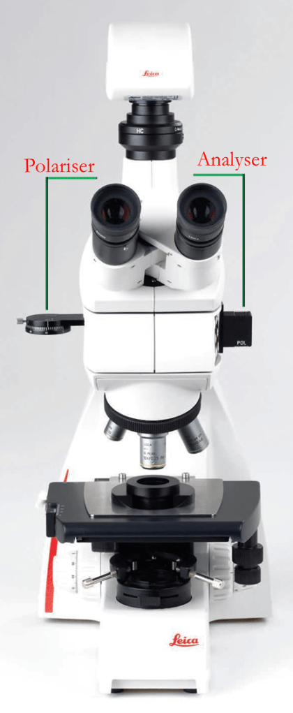
Polarising Filter (Polariser)
Position: The polarising filter, often simply called the “polariser,” is placed above the sample stage and below the polarising light source in the light path.
Function: The polariser converts unpolarised light from the illumination source into polarised light. This means it filters the light waves so that only those vibrating in a single plane pass through. The polarised light then interacts with the sample, which can affect its polarisation properties depending on the sample’s birefringence.
Polariser Ring and Its Function
Position and Purpose: The ring on your polariser that indicates 0 to 180 degrees is used to adjust the orientation of the polarised light. This adjustment is crucial for observing birefringent properties in the sample. The degrees marked on the ring correspond to the angle at which the polarising filter is oriented relative to the light path.
Function of the Ring
At 0 or 180 Degrees: When the polariser is set to 0 or 180 degrees, the light passing through is polarised in a specific plane. However, if the sample or the analyser is not oriented in a way that interacts with this plane of polarisation, the effect of polarisation might not be visible. Essentially, at these angles, the polarised light may not be effectively altered by the sample or the analyser, resulting in an image that appears similar to the non-polarised light conditions.
– At 90 Degrees: Setting the polariser to 90 degrees aligns it perpendicularly to the analyser (which is also at 90 degrees to the initial polarisation direction). This configuration maximises the interaction between the polarised light and any birefringent structures in the sample. Birefringent materials have different refractive indices along different axes. When polarised light passes through such materials, it splits into two rays that travel at different speeds and directions. The analyser, positioned at a 90-degree angle to the polariser, will block light that has not been altered in its polarisation. Only light that has been affected by birefringent structures (changing its polarisation state) will pass through, creating contrast. Therefore, areas of the sample that do not exhibit birefringence will appear black because the unchanged polarised light is blocked by the analyser.
How It Works:
- Polariser Adjustment: The ring allows you to rotate the polarising filter to different angles, effectively changing the orientation of the polarised light.
- Interaction with Sample: At 90 degrees, the maximum interaction occurs between the polarised light and the birefringent structures in the sample. This orientation makes birefringent areas appear bright and non-birefringent areas appear dark.
- Visualisation: By adjusting the polariser angle, you can optimise the visibility of birefringent properties. 90 degrees is the optimal setting for revealing birefringence because it ensures the polarised light interacts effectively with the sample and the analyser.
- Role in Imaging: The polarised light interacts with the sample, revealing structures and properties that are not visible with regular bright field microscopy.
Analyser
Position: The analyser is placed in the light path above the polarising light source. It is oriented perpendicular (at 90 degrees) to the polariser and positioned between the polarising light source and the camera.
Function: The analyser is another polarising filter (this is why it is marked as ‘POL’ in the microscope), but it is oriented perpendicular (at 90 degrees) to the polariser. It analyses the light that has passed through the sample. The analyser allows only light that has been altered in its polarisation by the sample to pass through. If the sample has birefringent properties, it will change the polarisation state of the light, which will then be detected by the analyser.
Role in Imaging: The analyser helps to detect changes in the light’s polarisation caused by the sample. This creates contrast in the image, highlighting birefringent structures that are not visible in non-polarised light.
Combined Use:
With Both Polariser and Analyser: When both the polariser and analyser are in place, the setup can reveal birefringent properties of the sample. Areas of the sample that change the polarisation state of the light will appear bright against a dark background, providing detailed information about the molecular structure and alignment.
Without the Analyser: If the analyser is removed, the system will not detect changes in polarisation, and the entire field of view will appear uniformly illuminated (typically with a blueish tint) without highlighting birefringent structures.

Step-by-Step Procedure (Leica DM750)
Sample Preparation:
– If you see dirt on the microscope lens, clean it with the spray duster before use.
– Prepare the solution/gel sample and place it on a clean microscope slide.
Microscope Setup:
– Turn on the microscope and computer (password: Hydrogel), and launch the imaging software INFINITY ANALYZE 7. We have two cameras connected to the computer. 189157 is connected to the Leica and 189159 is connected to the Nikon. Select the one you want to use. Note that we can’t collect images from both of the microscopes at the same time since we use the common computer.
Capturing Bright Field Images
1. Bright Field Illumination:
– Turn on the white light source located at the bottom of the microscope stage.
– Place the prepared microscope slide with the hydrogel sample on the stage.
– Go to an empty space on your slide and click on the “white balance” button in the software to see the true colour of your sample.
2. Focusing the Sample:
– Use the coarse and fine focus knobs to bring the sample into focus under low magnification.
– Switch to higher magnification if needed and adjust the focus to obtain a clear image of the hydrogel fibres.
3. Capturing the Image:
– Adjust the brightness and contrast of your sample by controlling the intensity of the illuminated light, and the “Exposure (ms)” level in the software to optimise the visibility of the hydrogel fibres.
– Capture the image by clicking the “📷 Capture” button on the software. The image will be displayed on the computer screen.
– Save the image with an appropriate filename and format.
Capturing Polarised Light Images (With Analyser)
4. Polarised Light Illumination:
– Turn off the white light source at the bottom of the stage.
– Turn on the polarised light source from the top of the microscope.
5. Inserting the Analyser:
– Check if the analyser is attached to the light path above the sample (this should be always on).
6. Focusing the Sample:
– Focus the sample using the coarse and fine focus knobs. If there is no birefringence, the image will appear black.
– Adjust the sample orientation to highlight birefringent structures, which will appear as bright regions against the black background.
7. Capturing the Image:
– Adjust the brightness and contrast to enhance the visibility of birefringent regions. You can change the number of light sources, the intensity of the polarised light, and also adjust the “Exposure (ms)” level in the software.
– Capture the image and save it with an appropriate filename and format.
Capturing Polarised Light Images (Without Analyser)
8. Removing the Analyser:
– Turn off the white light source at the bottom of the stage.
– Ensure the polarised light source from the top is still on.
– Remove the analyser from the light path.
9. Focusing the Sample:
– Focus the sample using the coarse and fine focus knobs.
– The image will display a blueish tint with a blue background, providing contrast for the fibres.
10. Capturing the Image:
– Adjust the brightness and contrast settings as necessary.
– Capture the image and save it with an appropriate filename and format.
Final Steps:
11. Cleaning and Storage:
– Carefully remove the microscope slide from the stage.
– Clean the microscope stage and objective lenses if needed.
– Turn off the microscope, making sure that both the bright field lights and polarised lights are OFF.
12. Documentation:
– The images should be stored in the C drive, under the folder “data”. Unfortunately, the images do not contain conditions and parameters for each captured image, like scale, magnification, light source settings, and any adjustments made. So, it is important that you keep a note of each relevant detail.
Following this procedure will ensure consistent and high-quality imaging of hydrogel fibres using the Leica 750 polarised microscope. The same process can also be applied to the Nikon microscope.
Adding a scalebar
Follow the steps below to add a scalebar to your image using ImageJ or PowerPoint:
ImageJ:
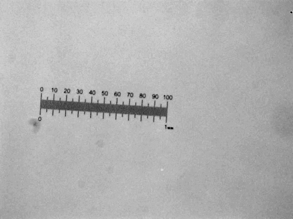
- Take an image of a known length at a specific magnification in the microscope. For example, this is a photo (on the right) of a 1 mm length taken at 5x magnification.
- Open the scale bar image in ImageJ – note this scale bar is for 5x magnification.
- Draw a straight line of chosen length using the scale bar (hold shift to ensure the line is straight).
- Go to Analyse > Set Scale.
- Input the known distance.
- Input the units.
- Tick global so ImageJ will apply these settings to all images.
- You can then insert the scale bar into images using Analyse > Tools > Scale Bar.
- You can edit the scale bar to make it show up clearly in your images.
- You can then apply your scale bar to all following images.
You need to do this every time you reopen ImageJ!!
PowerPoint:
- Insert the following scale bar image (at 5x magnification) into PowerPoint.
- Insert the image you need to add a scale bar to.
- Choose the size you want the image to be.
- Set the scale bar image to be the same size.
- Draw a rectangle along the scale bar to your chosen length.
- Paste this rectangle onto your image (see the example above – the scale bar is 300 μm in length).
Below are some images and scale bars provided at different magnifications.
By following these steps, you can add accurate scale bars to your images, ensuring precise measurement representation in your microscopy work
